Revised 02/09/2020
Geometry of a 3 Sided Bowl
This page will explore the geometry of a 3 sided bowl turned from a block of wood.
Why? Knowing about its geometry allows one to plan a turning before it is placed on the lathe. This may enable
the turner to make better use of the wood including the ability to make more than one item from the block.
This page is divided into the following sections:
Part 1: The Analysis
The analysis uses some very simple math all of which taught or used in high school geometry courses.
Lets look at what is used for the sake of anyone who has forgotten what they learned in their geometry
and earlier math classes.
- Square roots. For example, the square root of 9 is 3 because 3 squared is 9. We will use the notation
√9 = 3. We will do the algebra for you so you can
follow the work even if you have forgotten how to manipulate square roots. But if you are interested, you may recall
√ab =
√a√b,
√a/b =
√a/√b and
√a2 = a. Typically we avoid writing
square roots in denominator. This can be done by a technique called rationalize the denominator.
      1/√a = (1/√a) x (√a/√a)
           = √a/a
- The Pythagorean theorem. It applies to right triangles with a 90o right angle. It states that
the square of the length of the long side, called the hypotenuse, equals the sum of the squares of the
lengths the two shorter sides. If we
use c for the length of the hypotenuse and a and
b as the lengths of the other 2 sides, the mathematical notation for
this rule is
c2 = a2 + b2
or
c = √a2 + b2.
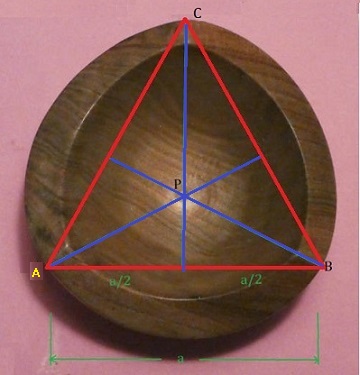
- Equilateral triangles. Equilateral triangles are triangles with 3 equal sides. If you look at the
picture on the left
which is the top view of a 3 sided bowl, you can see why they are relevant. We see the red lines connecting
the 3 corners of the bowl form an equilateral triangle which has some very helpful
properties. The corners, called vertices of the triangle are denoted by
A, B, and C.
The blue lines are perpendicular (right angle) to the red lines and meet at point P,
the so-called center of the triangle.
These lines bisect the corresponding red lines dividing them in half. The lines from
P to the vertices are called
circumradii. If we denote the length of the sides by a, the length of a
blue line (called an altitude) is a√3/2
and the length of a
circumradius (like PC) is 2/3rds of that length, namely
a√3/3.
One last comment. We say the equilateral triangle is
inscribed in the circle formed by the outside of the bowl.
If desired, you can review the properties of equilateral triangles in web pages such as
https://brilliant.org/wiki/properties-of-equilateral-triangles
or even
https://en.wikipedia.org/wiki/Equilateral_triangle.
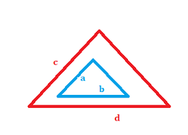
- Similar. In geometry similar objects have the same shape. One is just an enlargement of the other.
In the figure on the right, the red and blue figures are similar and the linear dimensions are proportional. Thus,
if a, b, c, and
d are lengths of their sides, then a/b = c/d.
-------
Turning a normal 3 sided bowl is fairly a standard technique that does
not require any special knowledge of its geometrical properties. But
knowing some may allow advanced variations of this shape
and/or more economical use of the cube allowing one to turn multiple objects from
the same cube.
Consider Figure 1 shown on the left. A cube with edges of length
s is shown. Five of its eight
vertices (corners) are marked V, V',
A, B, and C.
We would place the cube in the lathe using the opposite vertices
V and V' and the
dashed line becomes the center line about which the cube is rotated. Then vertices
A, B, and C
are in a plane perpendicular to the center line axis of rotation. This
plane is outlined in red and lightly shaded. A,
B, and C are the three vertices closest
to vertex (corner) V.
Using the Pythagorean theorem
(c2 = a2 + b2),
we can determine that the length of the diagonals
such as the lines AC, AB and
BC across sides of the cube have length
s√2, that is, s times
the square root of 2. Using the theorem a second time one can determine the diagonals between
opposite vertices such as between V and V'
have length s√3, that is,
s times the square root of 3.
Now let us assume that we cut the cube along the plane containing the vertices
A, B, and C.
The result is shown in Figure 2. The boundary lines are shown in red as in the previous figure. These lines are
diagonals of a side of the cube and we have determined their length is
s√2.
Because all of its sides have equal lengths, the triangle ABC is an equilateral
triangle.
One of the basic properties of equilateral triangles says that if you draw the vertical line though
C, it will bisect the line AB, so each
half of the base has length s√2/2.
If we draw the same lines through vertices A and B,
the equilateral triangle
properties say that all of the lines will meet at one point P, the "center" of the triangle.
That point is significant as it is on the line that is the center of rotation for the entire blank. Applying some more well
known properties of equilateral triangles, we find that the lines from point P to the
vertices have length s√6/3.) (You check this out
using the normal formulas for an equilateral triangle, remembering each side of this triangle has length
s√2.)
That means that the theoretical radius of 3 sided bowl is
s√6/3 and its diameter is
2s√6/3. This ignores any rounding of the corners,
sanding, or off centering when placing the cube or the parts in the lathe.

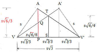
Now that we have the radius and diameter of the bowl, we turn to the horizontal spacing of the vertices and Figure 3.
A word about that sketch. The upside down "W" shape is top half the shape that one would see when the cube is
turning on the lathe.
Actually vertices A and A' never line up. If vertex
A is on top, then turning the cube 60o
or 180o would bring vertex
A' to the position shown. Or you may think of the lines
VA'and A'V' as being the inverted bottom half
of the cube which is not shown in Figure 3.

A spinning cube
We know the hypotenuse of the right triangle with vertices V,
P, and A has length
s and the vertical line side through A has length
s√6/3. Using the Pythagorean theorem again,
we determine that the bottom
of the triangle has length s/√3 or equivalently
s√3/3.
By symmetry, the other end at V' has the same length. That is neat because each is 1/3 of the length
of the line between the vertices. So the distance between the vertices A and
A' is also the same! That means we have the two most important measurements
for the 3 sided bowl.
We will now get one more measurement that might be useful. We will determine the radius of the blank at its
midpoint - its "waist". That is where the two sloped lines meet at T. We observe that
the two right triangles VQP and VTS are similar - they have
the same shape even though they have different sizes. The sides have the same ratio. Thus,
QP/VP = TS/VS. Substituting and simplifying gives
TS = s√6/4. The diameter of the blank at that point is twice that or
s√6/2.
Unfortunately because of the square roots, some people may find these formulas difficult to use.
An Excel like spreadsheet in Dimensions of 3 Sided Bowl provides a convenient
table of calculations for various sized cubes.
Go to top of page
Part 2: Using the Analysis
We have three examples, showing how the formulas in Part 1 can be used to help
by showing the feasibility of turning 3 sided bowls in a given cube and how the part
or parts can be arranged. In each case, multiple items are turned from a single
cube of wood.
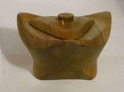
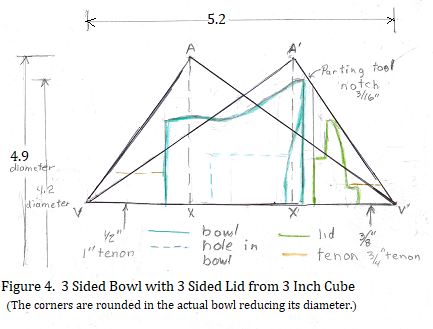
Example 1: This is the example that motivated the study of the geometry of 3
sided bowls. Before starting on this bowl, I wanted to know if it was indeed possible
to turn a bowl and lid from the same cube, and if so, how to organize the parts. An
additional problem was the available cube was only 3 inches on each side. The
formulas for the bowl length, vertex spacing and radius of the points allowed me to
make a full sized drawing like the one shown in Figure 3 and graphically answer
those questions. Figure 4 shows the top half of the block with bowl turned on its
side as it would be in the lathe. I found that I could use 1 inch diameter (1/2 inch
radius) tenon for the bowl and a 3/4 inch diameter (3/8 inch radius) tenon for the lid.
Fortunately, I have a set of #1 jaws for my 4-jaw chuck because it would not have
been possible to turn the bowl in such a small cube using the more standard #2 jaws.
The #1 jaws can grip the small diameter tenons that were used. The tenons are rather
long to help prevent the bowl or lid from flying out of the jaws. The lid handle was
turned from the lid's tenon after the lid was pulled part way out of the jaws. The top
fits into a 1-1/2 inch hole drilled with a sequence of forstner bits.
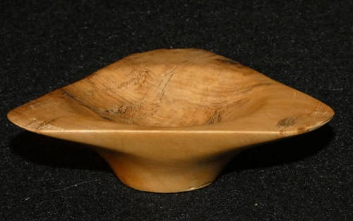

Example 2: Another question was "Is it possible to turn 2 bowls from 1 cube?"
It turns out that it is possible although the resulting bowls are so shallow, it might be
better to call them "saucers". Figure 5 shows the 2 saucers facing each other. The
layout includes notches for the parting tool used to separate the bowls. Prototypes
were turned from a very small cube about 2-1/2 inches on a side. The Prototypes
proved the possibility although I broke a corner off the second bowl and it turned out to
be circular bowl instead. Both bowls are less than 1 inch in height.
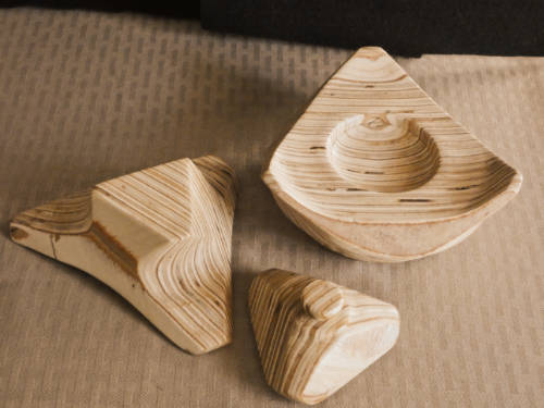

Figure 6. Two bowls and a lid from one 4 inch cube
Example 3: While working on the analytics of 3 sided bowls, it occurred to me that it
would be possible to use an alternate arrangement of the bowls and even include a lid
for the one of the bowls. As shown in Figure 6, the two bowls are oriented in the
same direction instead of facing each other. The drawings showed that at least a 4
inch cube would be needed. The two bowls are not identical. It is doubtful that one
could turn this arrangement without planning using the analytical formulas. Getting 3
items from 1 cube is pretty economical use of the wood.
Update: I hadn't had time to try this example when this page was originally written. Now
I have and the result is shown above. The pieces were turned from a 4-1/2 inch cube. Actually this
was a double experiment. It was turned from a cube constructed of pieces of 1/4 inch
plywood underlayment glued together. There was some problems with the plywood
delaminating. If you look carefully, you can see one corner of the left piece in the picture
(which was the right hand piece in Fig. 6) is missing.
I would probably try to use better plywood in the future. I didn't
follow the plan exactly. But it shows that the idea would actually work. Moreover,
the shallower bowls are easier on one's fingers during the turning and sanding process than
a deeper, standard 3-corner bowl. The lid looks better than
the bowl used in Example 1. Another picture of the bowl with one piece used as a stand is
shown in this picture.
Hint to anyone who tries this. When turning 3 cornered bowls form a cube made of plywood,
significant and parts of the top and bottom face may show up in the bowls. This was particularly
true in this 3 part set as can be seen in the above picture. Make sure the top
and bottom are nice before gluing. Stack the plywood
pieces to see how high the cube will be and cut the squares a little larger than that height.
After gluing you will have to trim the sides but hopefully not the top and bottom to make a cube. Sand
the sides to make them smooth before turning. Sanding the surfaces before turning is much
easier than sanding the flat surfaces after turning.
Go to top of page
Part 3: Determining the Diameter of a Completed 3 Sided Bowl
Determining the diameter of completed 3 sided bowl is rather difficult
because it cannot be easily measured. Moreover, that diameter often cannot be
determined theoretically because of breakage of a point or rounding of those points
during turning and/or sanding process. However, assuming that the distances between the
points is equal, they still form an equilateral triangle. Hence the ratios shown in
Figure 2 are still valid even though the value of s may not be.
Recall that in Figure 2,
the distance PC was called the circumradius which
is half the diameter of a circle circumscribed about the triangle. Observe
   diameter of a completed bowl  = 2 times the circumradius
                                 = 2(s√6/3)
                                 = 2s√6/3
Figure 2 shows the distance between the points of the bowl is
s√2.
   diameter of a completed bowl   2s√6/3
   ---------------------------- = ------
   distance between the points     s√2
Solving for the diameter and simplifying the fraction and square roots, we see
   diameter of a completed bowl  = 2√3/3 times the distance between the points
                                 = 1.1547 times the distance between the points
If the points are rounded, one can still determine the best center of the rounded corner and use this formula.
Go to top of page
Part 4: (Optional) 3 Sided Bowl Angles
This section discusses some additional properties of 3 side bowls - their angles. These results might be useful
when setting a cube to be turned or may be of interest to those who are just interested in the bowl's geometry.
We will be using some trigonometry - namely the tangent function. When I was in high school many years
ago, that topic was covered in a more advanced high school course but it is often covered at the end of a
geometry course now. So we are not really violating the statement in Part 1 that claimed that all the math used
in this page is normally covered or used in high school geometry. The following are two more basic geometric
principles that will be needed.
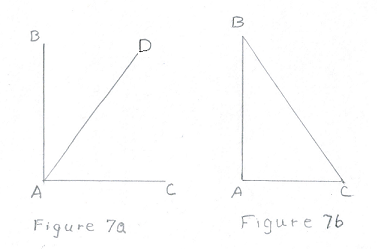
- Complimentary angles. Two angles are complimentary if the measures of those angles add
up to 90o. Figure 7a below shows the most common example. Angle
 BAC is a right angle and angles
 BAD and
 DAC are complimentary. Figure 7b
illustrates the second most common example of complimentary angles assuming the angle at
A is a right angle (90o).
It is known that the measures all three angles in a triangles in triangle add up to
180o. That means that the measures of angles at
B and C add up to
90o and the angles are complementary.
- Tangents. Note: Greek letters such as α,
β, and θ are normally
used for angles in trig instead of multi character names like
 BAC or
 A.
A.
Consider the triangle in Figure 8. The tangent of an angle θ,
commonly written
tan θ; is defined as the ratio of the length of the opposite side to
the length of the adjacent side. That is,
tan θ = opp/adj
In this paper we will know the lengths of opp and adj sides
and will want to determine the angle θ. This is done with
the arctangent function commonly written as arctan or
tan-1. Thus,
tan-1(opp/adj) = θ
For example, suppose angle θ = 53.31o
tan θ = tan 53.31o = 1.5
The sides opp and adj might be 1.5 and 1,
3 and 2, or even 300
and 200, for example. And
tan-1 1.5 = tan-1 (3/2) = tan-1 (300/200) = 53.31o
If you have a scientific calculator and it is in the degree mode, you would generally press the
tan button
to calculate the tangent of an angle and a button such as INV or
2nd followed by the tan button in order
to calculate an arctan, the angle corresponding to the given ratio.
Now that we have the basic math needed, we can determine the important angles in a 3-sided bowl.
------
We want to find α1,
α2 and γ.
By looking at the figure, we observe that by symmetry the two
angles labeled α1 are equal justifying the labeling.
Lets first look at
α2. Triangle VAP is a right triangle so we
observe that
       tan α2  = AP/VP
               = (s√6/3)/(s√3/3)
               = √2 = 1.4142135
after cancelling, rationalizing the denominator, and using some properties of square roots. We find
α2 = tan-1 1.4142135
and by using scientific calculator, we find
α2 = 54.74o
The calculation of α1
is almost the same except the denominator of the fraction is twice as big.
       tan α1  = A'P'/VP'
               = (s√6/3)/(2s√3/3)
               = √2/2 = 0.7071067
Using tan-1, we determine
α1 = 35.26o
If we add the values for α2
and α1, we find the sum is
90o and the
angles are complementary!
Now that we have α2
and α1, we can find
β1 and
β2 easily.
Recall that triangle VAP is a right triangle so
α2 and
β1 are complimentary and their measures
add to 90o.
Likewise, triangle V'AP is also a right triangle so
α1
and β2 are also complimentary. Thus,
α2 + β1 = 90o α1 + β2 = 90o
Solving for the
βs, we obtain
β1 = 90o - α1 = 35.26o,
β2 = 90o - α2 = 54.74o.
Again, these angles add to 90o and are also
complementary and together from a right angle.
So γ = 90o. Thus the angle at the point of the 3
sided bowl is a right angle (assuming the turning and sanding process has not changed the angle). The
angle is a right angle of the original cube.
Go to top of page
Part 5: Using the Angle Analysis
to make a jig to cut corners from the cube.
(I plan to replace the photos in this part with ones that show a cube cut from a nicer piece of wood.)
If the math is over your, you can check out how to construct and use a jig if you click
here.
The α and β angles
found in the previous section, have an application that might be helpful
to some turners. Normally, when turning a 3 sided bowl,
the cube's opposites corners are placed in the lathe without any special attachments to center the cube.
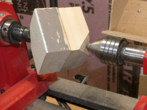
But a few turners may want to turn it on centers using a drive center and 60 degree live center like they
would use to turn a spindle as shown on the right. In order to use
these attachments, one needs to cut off two corners of the cube, perpendicular to the axis of rotation. But
cutting those corners off precisely is quite difficult. In this section, we will discuss a way of doing this
taking advantage of the values found for those angles in the previous section.
In
http://www.armadillowoodworks.com/pdfs/three_sided_bowl.pdf, Craig Timmerman pictures a jig
he uses with a band saw to cut off corners of cubes but unfortunately, gives no details on
how it is built and used. Fortunately, we can use the angles found in the previous section to build and use a
different but simple jig
to cut corners of a cube on a table saw. The jig could be adapted to be used on a band saw or even
could be adapted to build a miter box and cut the corners by hand. First a look at the geometry.

Figure 10
Now, lets look at Figure 10. There are a couple of ways to interpret this figure. The first is that
it is similar to
Figure 9 except that vertex A' has been rotated
180o down into its actual position. That
means angle α1 points downwards instead of
upwards. A new construction line QQ' has been added. Right
triangle marks have been added at vertices V,
A, and Q and new angles
θ1,
θ2 and ω
have been specified.
Our goal is to determine angle θ1 which
turns out to be most useful with the jig.
In Part 4, the lines AP and AQ
were drawn perpendicular to line VV'. Also recall,
we showed that α2
and α1 are complimentary. That is, their
sum adds to 90o justifying the right angle mark at
vertex V. Likewise,
β1
and β2 are complimentary and vertex
A is also a right angle. We also showed
α2 = β2 and
α1 = β1.
Because α1 = β1,
right triangles VPA and QPV
are similar triangles. This means
θ2 = α2. The line
QQ' was constructed perpendicular to
VA' so
θ1 and
θ2 are also complimentary, their sum
adds to 90o so
ω is also a right angle.
This means that
      θ1 = β1 = α1
         = 35.26o.
Now lets look at figure 10 in second way. Set the cube so that vertex
V is the bottom, left, front corner of the cube and
V' is its top, right, back corner. Vertex
A' would be on the bottom below vertex
V'. Cut the cube diagonally along the plane formed by vertices
V, A' and
V' which is perpendicular to the bottom and at a
45o to the front of the cube. The result would be
what we see in Figure 10 although Figure 10 would have to be rotated counter clockwise by
an angle of α1.
Set the half cube on a table saw, perpendicular to the blade. If we tilt the blade by the
angle θ1 = 35.26o we see that it could cut a corner
of cube at an appropriate angle. What we need is to hold the whole cube at the
45o angle.
The jig
Even if the above analysis is over your head, you should be able to follow the construction of
the jig to cut the corners at the 45o angles.
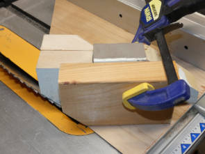
A simple jig that does this shown in the left hand picture above. Piece of 2 by 4 has been
fastened to a thin sheet
of plywood panel at a 45o angle to the right side.
The right side is pushed along a rip fence. The panel and part of the 2 by 4 was cut about
8-1/2 inches wide with the blade set at a
set at a 35.26o angle. The corners are
cut with the blade at the same angle. The right
hand picture shows the
jig in use. (One corner of the cube has already been cut off.) The cube is placed in the jig as
shown and held in place by a second small piece of 2 by 4 clamped
to the longer fixed piece at location determined by the size of the cut corner and pushed pass
the turning blade.

The result is shown on the right. A corner was cut off. The corner has the shape of an
equilateral triangle which is accurate to best that can be measured. The photo also shows a
way to find the center of the triangle. The center of each side was marked and a line drawn
to the opposite corner. The lines meet at the center point.
Notes:
- The width of the bottom panel was designed to allow a 6 inch cube. However,
if one really plans to use cubes bigger than about 4-1/2 inches, consider using
2 by 6 pieces instead of 2 by 4 pieces and a wider bottom
board to simplify the clamping of larger blocks.
- The fixed
2 by 4 was cut at the angle shown to provide better support for the cube as it is cut and also
to provide a crude check that the blade is angled correctly.
- If a band saw is used, the same jig can be used but one would tilt the table instead of the
blade. Some way of supporting the jig such as a rip fence would be needed to keep the jig from
sliding off the table.
- If a band saw was used, the cuts were accurate enough and if planning as in Part 2 was used,
then the cube could be cut with the band saw in advance instead of having to use a parting tool as
suggested in that part.
- If one wants to cut the corners by hand, one could build a specialized miter box that would
hold the cube at a 45o. A slot would be needed
to cut the cube at the required angle.
Go to top of page
|
|
|
|
|
|
|
|
|
Dimensions of 3 Sided Bowl
|
|
|
|
|
|
|
|
|
|
Length of side
|
Length of diagonal
|
Length between vertical points
|
Bowl radius*
|
Waist radius**
|
Bowl diameter
*
|
Waist diameter**
|
|
2 |
3.46 |
1.15 |
1.63 |
1.22 |
3.27 |
2.45 |
|
2.25 |
3.90 |
1.30 |
1.84 |
1.38 |
3.67 |
2.76 |
|
2.5 |
4.33 |
1.44 |
2.04 |
1.53 |
4.08 |
3.06 |
|
2.75 |
4.76 |
1.59 |
2.25 |
1.68 |
4.49 |
3.37 |
|
3 |
5.20 |
1.73 |
2.45 |
1.84 |
4.90 |
3.67 |
|
3.25 |
5.63 |
1.88 |
2.65 |
1.99 |
5.31 |
3.98 |
|
3.5 |
6.06 |
2.02 |
2.86 |
2.14 |
5.72 |
4.29 |
|
3.75 |
6.50 |
2.17 |
3.06 |
2.30 |
6.12 |
4.59 |
|
4 |
6.93 |
2.31 |
3.27 |
2.45 |
6.53 |
4.90 |
|
4.25 |
7.36 |
2.45 |
3.47 |
2.60 |
6.94 |
5.21 |
|
4.5 |
7.79 |
2.60 |
3.67 |
2.76 |
7.35 |
5.51 |
|
4.75 |
8.23 |
2.74 |
3.88 |
2.91 |
7.76 |
5.82 |
|
5 |
8.66 |
2.89 |
4.08 |
3.06 |
8.16 |
6.12 |
|
5.25 |
9.09 |
3.03 |
4.29 |
3.21 |
8.57 |
6.43 |
|
5.5 |
9.53 |
3.18 |
4.49 |
3.37 |
8.98 |
6.74 |
|
5.75 |
9.96 |
3.32 |
4.69 |
3.52 |
9.39 |
7.04 |
|
6 |
10.39 |
3.46 |
4.90 |
3.67 |
9.80 |
7.35 |
|
Item |
Formula |
Comment |
|
Length of side |
s |
Length of side of cube, VA |
|
Length between vertical points |
s√3/3 |
Length of AA' 1/3 of length of diagonal
VV' in diagram |
|
Bowl radius*
|
s√6/3
|
PA in diagram |
|
Bowl diameter* |
2s√6/3 |
Double of bowl radius |
|
Waist radius** |
s√6/4 |
ST in diagram |
|
Waist diameter** |
s√6/2 |
Double of waist radius |
* The Bowl radius and diameter are the theoretical diameter. In practice, because of
sanding, rounding corners, and other factors, it will always be smaller.
** The waist radius and diameter are the diameter in the middle where the left and right
slopes meet at point T.
Go to top of page
Maintained By: James Brink (brinkje@plu.edu).



 BAC
BAC